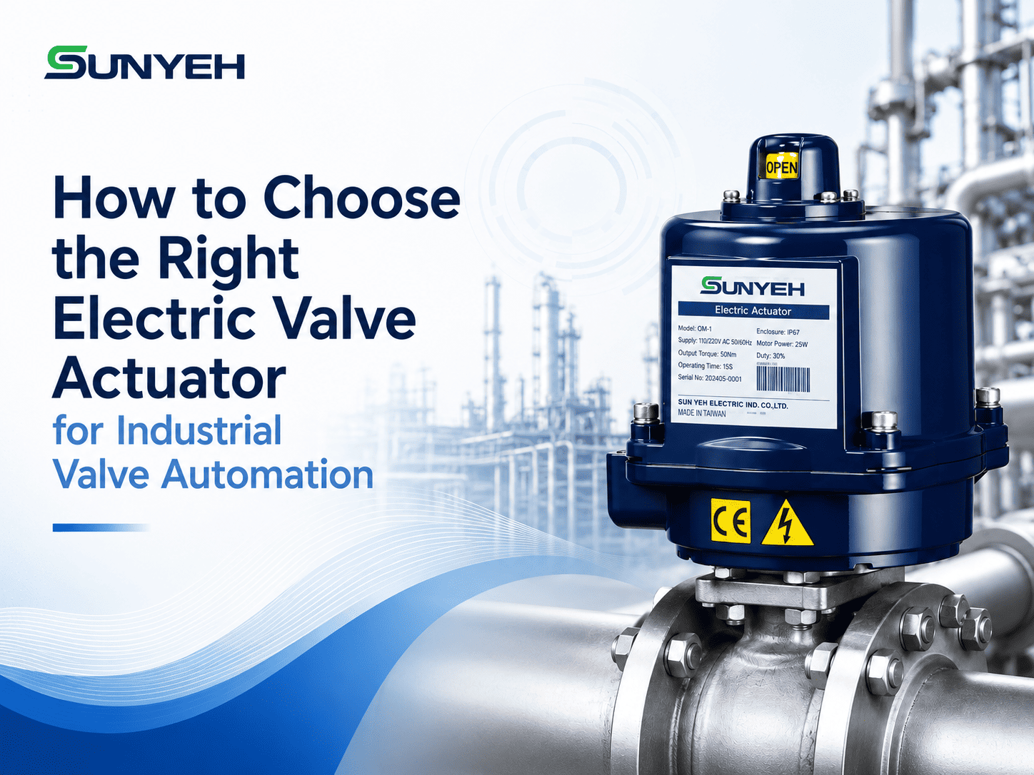
How to Choose the Right Electric Valve Actuator for Industrial Valve Automation
Selecting the right electric valve actuator starts with the valve itself—not with actuator price, physical size, or the number of available features.
For industrial buyers, engineers, OEMs, and system integrators, the key is to match the valve’s movement, required torque or thrust, control method, operating environment, and safety requirements with the appropriate actuator configuration.
This guide focuses specifically on the actuator selection process. For a broader explanation of how electric actuators support valve automation, see Why Electric Actuators Are Essential for Valve Automation .
1. Start with Valve Motion: Which Electric Valve Actuator Type Fits the Valve?
Different valve structures operate in different ways. Matching actuator motion first helps narrow down the correct actuator category and reduces the risk of mechanical mismatch during installation.
| Valve Motion | Common Applications | Actuator Direction |
|---|---|---|
| Quarter-turn | Ball valves, butterfly valves, plug valves, many dampers | Quarter-turn electric actuator |
| Multi-turn | Valves requiring multiple shaft or stem rotations to complete operating travel | Multi-turn electric actuator |
| Linear | Globe valves and other linear-travel devices | Linear electric actuator |
SUN YEH provides several actuator platforms for these motion requirements. The OM Series and CM Series support quarter-turn valve automation, while the compact T Series provides lower-torque quarter-turn solutions for installations where space is limited.
For linear movement, the L Series Electric Linear Valve Actuators provide a thrust range from 250 to 2,000 kgf. SUN YEH product literature also includes multi-turn actuator solutions for applications requiring multiple rotations.
2. When Is a Quarter-Turn Electric Actuator the Right Choice?
Quarter-turn valve automation is common in water systems, HVAC, cooling systems, industrial process lines, and airflow control. However, confirming a 90-degree movement only identifies the actuator category—it does not determine the final model.
Engineers and buyers should also confirm:
- Required operating torque
- Breakaway torque
- Valve type and size
- Process pressure
- Media characteristics
- Control mode
- Operating speed
- Installation space
- Environmental protection requirements
SUN YEH’s OM Series covers a torque range from 35 Nm to 4,500 Nm, while the CM Series covers 100 Nm to 600 Nm.
For compact lower-torque installations, the T Series provides 6 Nm and 15 Nm models.
This is why buyers should avoid treating every quarter turn electric actuator as interchangeable. Two actuators may both provide quarter-turn movement but differ significantly in torque range, mounting dimensions, control configuration, operating speed, manual override, and environmental suitability.
3. Size the Actuator by Torque or Thrust—not Valve Size Alone
Two valves with the same nominal size can require different actuator output because operating resistance may vary with pressure, sealing design, valve construction, process media, and valve condition.
For rotary valves, one particularly important value is breakaway torque—the torque required to initiate valve movement from the seated position.
Ignoring breakaway torque can result in an actuator that appears suitable based on nominal valve size but cannot reliably begin valve movement under real operating conditions.
For linear applications, output is evaluated as thrust. SUN YEH’s L Series provides 250 to 2,000 kgf of thrust, with maximum stroke depending on model.
Final actuator sizing should be based on verified valve data and project engineering requirements rather than simply selecting a larger actuator without technical justification.
4. Match Control Method, Power Supply, and Feedback to the Automation System
On/Off Control
On/Off control is suitable when the valve only needs to move between fully open and fully closed positions. Typical examples include isolation and basic flow switching.
Modulating Control
Modulating control is required when the valve must move to intermediate positions for flow, pressure, temperature, or other process regulation.
For example, SUN YEH’s CM Series uses open/close control as standard and offers modulating control as an option, while the L Series is designed with modulating control as a standard feature.
Before ordering, the project team should also confirm:
- Operating voltage
- Control signal
- Required position feedback
- Wiring requirements
- PLC, BMS, DCS, or other system compatibility
- Duty conditions
5. Add Fail-Safe or Explosion-Proof Requirements Only When the Application Demands Them
When Is Fail-Safe Required?
If the system requires a valve or damper to move to a predetermined safe position after loss of electrical power, a fail safe electric actuator should be specified at the beginning of the project.
SUN YEH provides two different fail-safe approaches:
When Is Explosion-Proof Protection Required?
Explosion-proof actuator selection becomes relevant when the actuator is installed in a classified hazardous area where flammable gases, vapors, or combustible dust may be present.
SUN YEH provides specialized solutions including:
- OME Series – explosion-proof quarter-turn.
- SE Series – explosion-proof spring-return fail-safe.
- LE Series – explosion-proof linear.
For hazardous-area projects, site classification, required certification, temperature range, enclosure requirements, and control method should be confirmed before a specific actuator configuration is selected.
6. Check Mounting, Environment, and Maintenance Before Finalizing Selection
Before finalizing the actuator model, confirm the physical connection between the valve and actuator.
- Mounting flange
- Output drive and valve shaft dimensions
- Coupling or adapter requirements
- Available installation space
- Wiring access
- Position indication
- Manual override requirements
SUN YEH’s OM Series , CM Series , and T Series use ISO 5211 mounting interfaces, while the L Series uses ISO 5210 flange interfaces.
The installation environment should also be reviewed for outdoor exposure, humidity, water, dust, corrosion, ambient temperature, vibration, and other site conditions.
Maintenance accessibility matters as well. If operators may need to reposition a valve during commissioning, servicing, or a power interruption, manual operation requirements should be considered during selection.
7. Electric Valve Actuator Selection Matrix: Match the Application to SUN YEH Solutions
| Application Requirement | Actuator Direction | SUN YEH Product Direction |
|---|---|---|
| Ball or butterfly valve automation | Quarter-turn electric actuator | OM Series / CM Series |
| Compact low-torque quarter-turn installation | Compact quarter-turn actuator | T Series |
| High-torque quarter-turn requirement | Quarter-turn actuator | OM Series |
| Multi-rotation valve movement | Multi-turn electric actuator | M Series / confirm current configuration with SUN YEH |
| Globe valve / linear movement | Linear electric actuator | L Series |
| Mechanical spring-return requirement | Fail-safe electric actuator | S Series |
| SuperCap fail-safe requirement | Electronic fail-safe actuator | DM Series |
| Hazardous-area quarter-turn application | Explosion-proof quarter-turn actuator | OME Series |
| Hazardous area + spring return | Explosion-proof fail-safe actuator | SE Series |
| Hazardous-area linear movement | Explosion-proof linear actuator | LE Series |
For B2B actuator inquiries, providing complete application data can significantly improve the selection process. Useful information includes:
- Valve type and model
- Required torque or thrust
- Operating pressure and media
- Required movement
- Voltage
- Control type
- Feedback requirement
- Fail-safe requirement
- Hazardous-area classification, if applicable
- Installation environment
- Mounting information
8. FAQ: Electric Valve Actuator Selection
Q1. What is the first thing to check when choosing an electric valve actuator?
Start with the valve’s required movement. Determine whether the valve requires quarter-turn, multi-turn, or linear motion before comparing torque, thrust, controls, or optional features.
Q2. When should I use a quarter-turn electric actuator?
A quarter-turn electric actuator is generally suitable for valves whose operating travel is approximately 90 degrees, including ball valves, butterfly valves, plug valves, and many damper applications.
Q3. Is valve size enough to determine actuator torque?
No. Valve size is only one factor. Required torque may also depend on pressure, sealing design, process media, valve condition, and breakaway torque. Valve manufacturer data should be used whenever available.
Q4. Do all valve automation applications need a fail-safe electric actuator?
No. Fail-safe capability is required when the system design specifies that the valve or damper must move to a predetermined safe position after power loss or another defined failure condition.
Q5. What information should I provide when requesting an electric valve actuator?
Provide the valve type, required torque or thrust, movement, operating voltage, control method, feedback requirements, mounting information, installation environment, and any fail-safe or hazardous-area requirements.
Conclusion
Choosing the right electric valve actuator is ultimately a matching process. The actuator must fit the valve mechanically, provide sufficient torque or thrust, communicate correctly with the automation system, and meet the environmental and safety requirements of the installation.
Sun Yeh Electrical Ind. Co., Ltd. provides electric actuator solutions for quarter-turn, linear, fail-safe, SuperCap fail-safe, and explosion-proof valve automation requirements, with additional multi-turn solutions available in its product portfolio.
Discuss Your Valve Actuator Requirements with SUN YEH
For valve manufacturers, OEMs, engineering companies, distributors, and system integrators, a clearer actuator recommendation starts with complete application data.
When contacting SUN YEH, prepare the following information whenever possible:
- Valve type
- Torque or thrust
- Stroke or rotation
- Operating voltage
- Control signal
- Feedback requirements
- Fail-safe position
- Hazardous-area requirements
- Duty conditions
- Installation environment
These project parameters allow SUN YEH to more efficiently evaluate an actuator configuration that matches the valve, automation system, and operating conditions.
